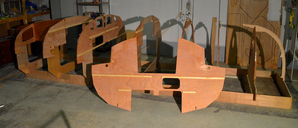
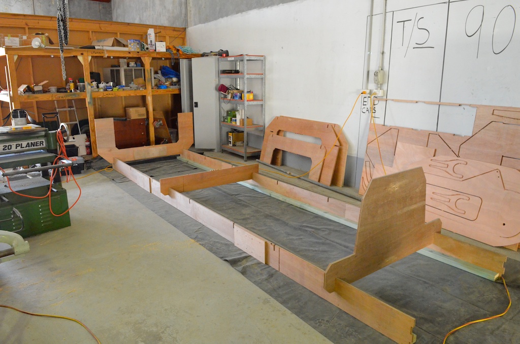
Planking the hull 1, keel and sole.
tony o'connor
It is my goal to have this hull planked by the end of July.
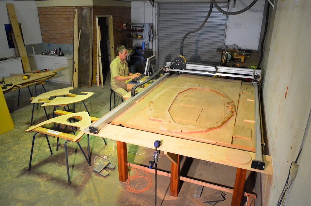
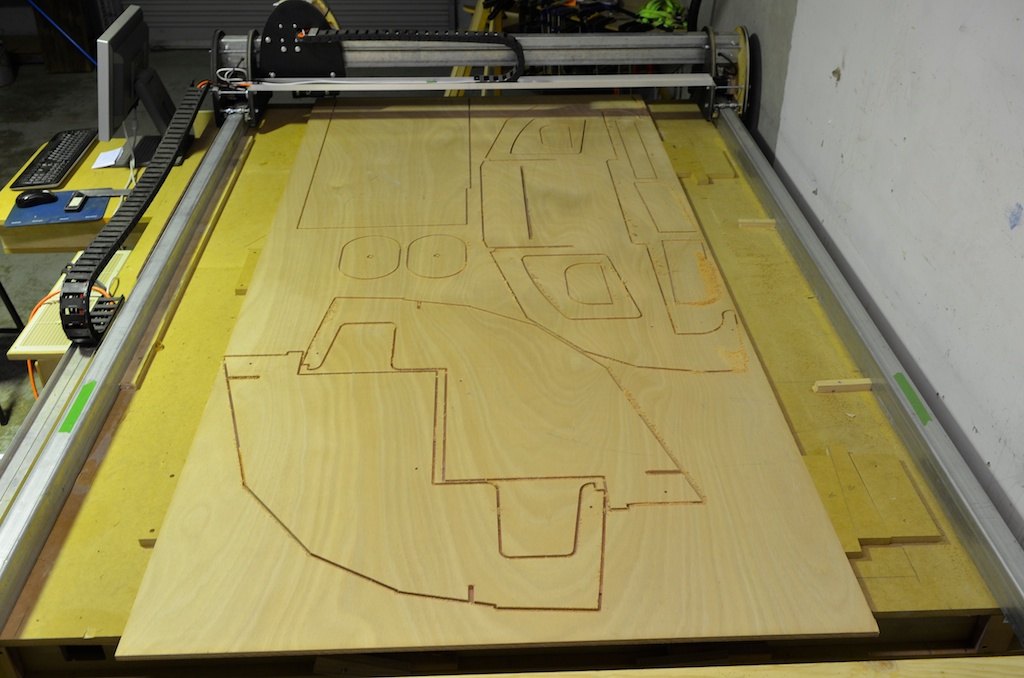
Since the planking is already cut on the cnc machine this shouldn't be too difficult except that before I can plank the hull I have to sheath the sole and garboard with two layers of glass cloth...and before I can do that I have to finish the keel.
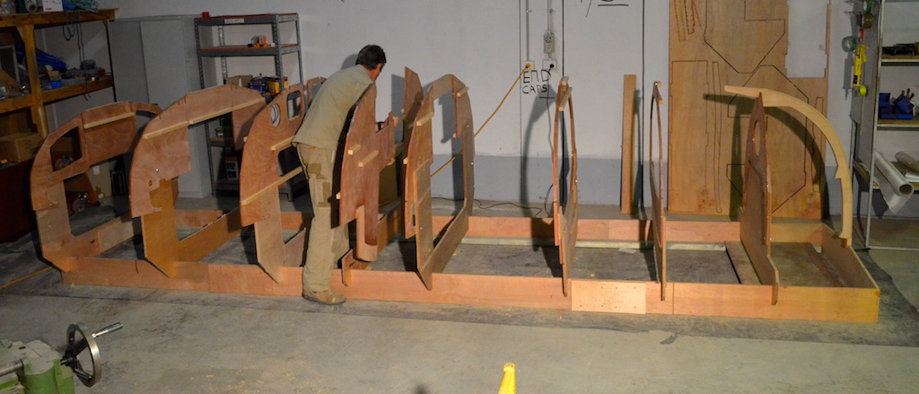
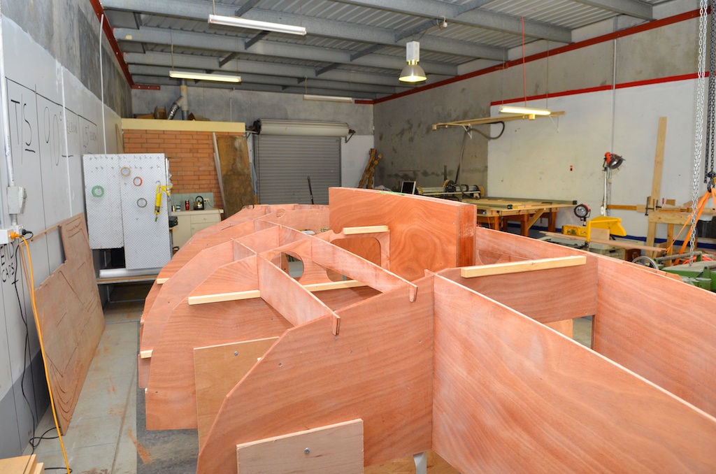
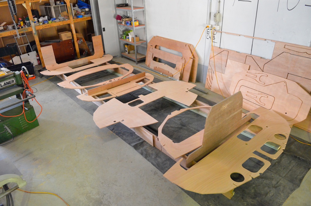
Fitting sole
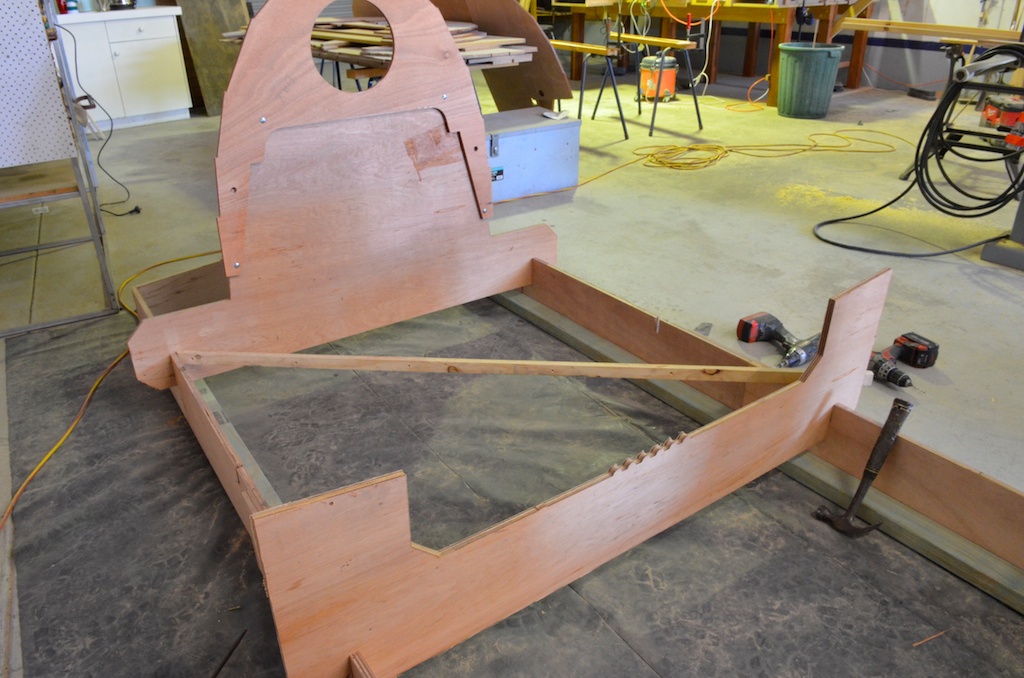
Fitting the sole.
The sole is made from two pieces joined just forward of the centerboard case, the elongated slots forward of the joint are for the keel itself, It slots nicely over the centreboard case, I cut a v-groove all around the cutout to allow plenty of glue around the joint.
Fitting ply doublers either side of the case, these will increase the width allowing room for required amount of ballast and also beef up the case side where the pivot pin will be.
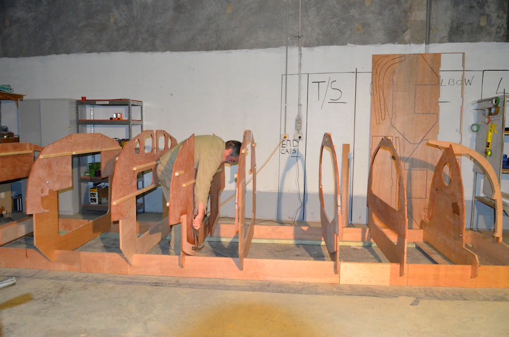
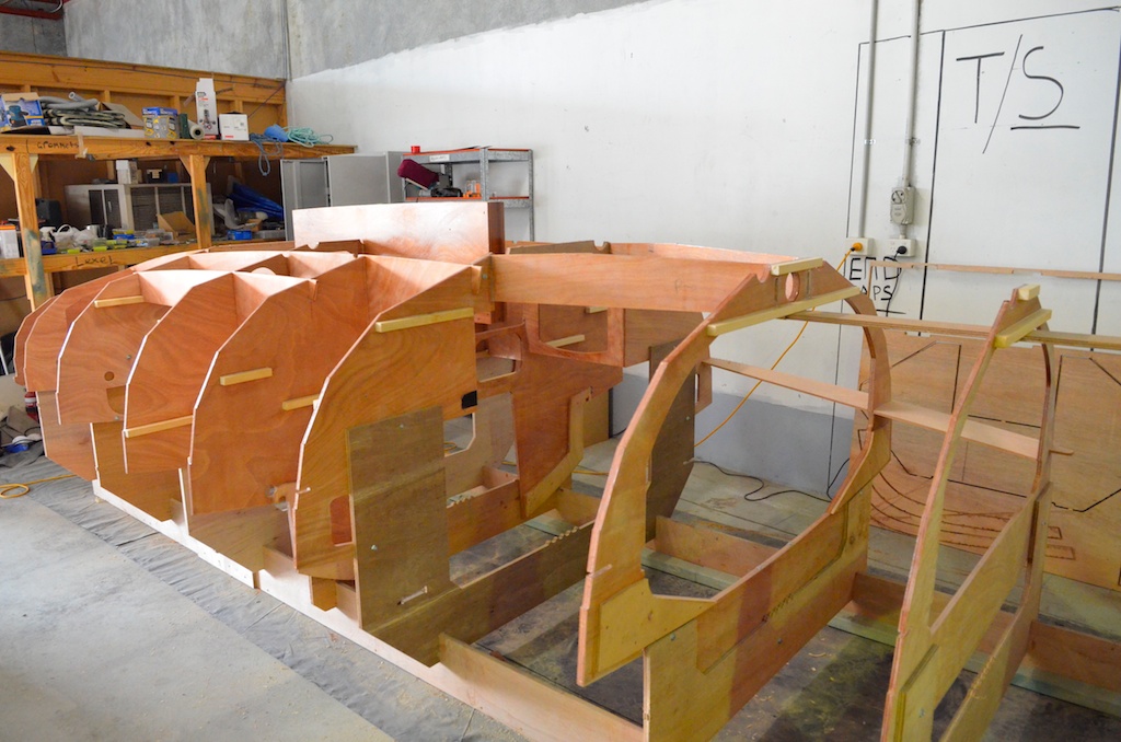
Next is the keel
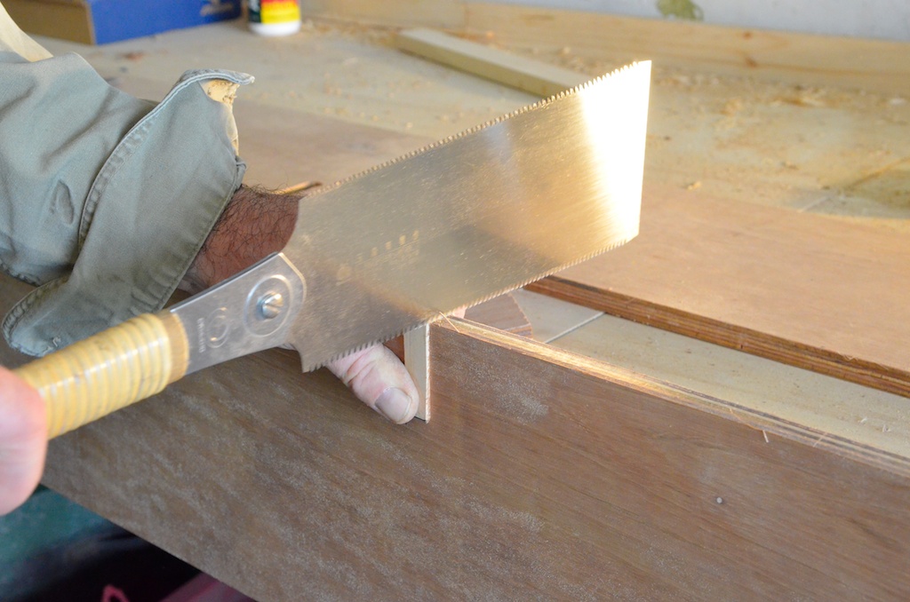
The keel sides are clamped to the centreboard case and also located with small mortices into slots cut into the sloe.
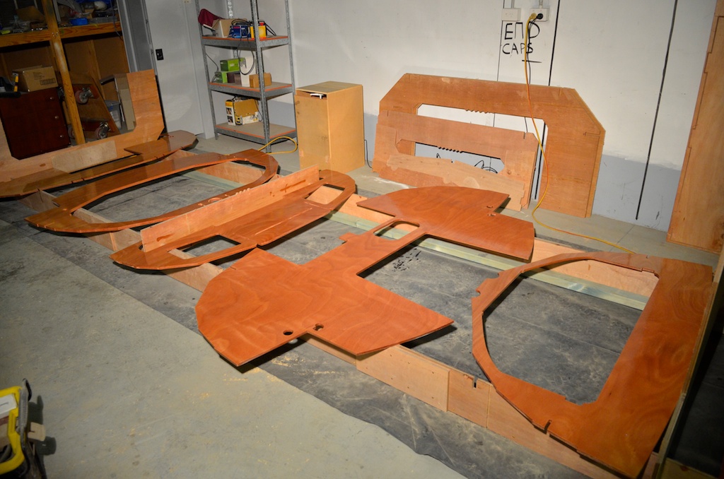
Each end has a "stem" a bevelled piece of wood that the sides are screwed to. The dimensions are in the plans. This piece is the first part of the building process that required any shaping with hand tools.
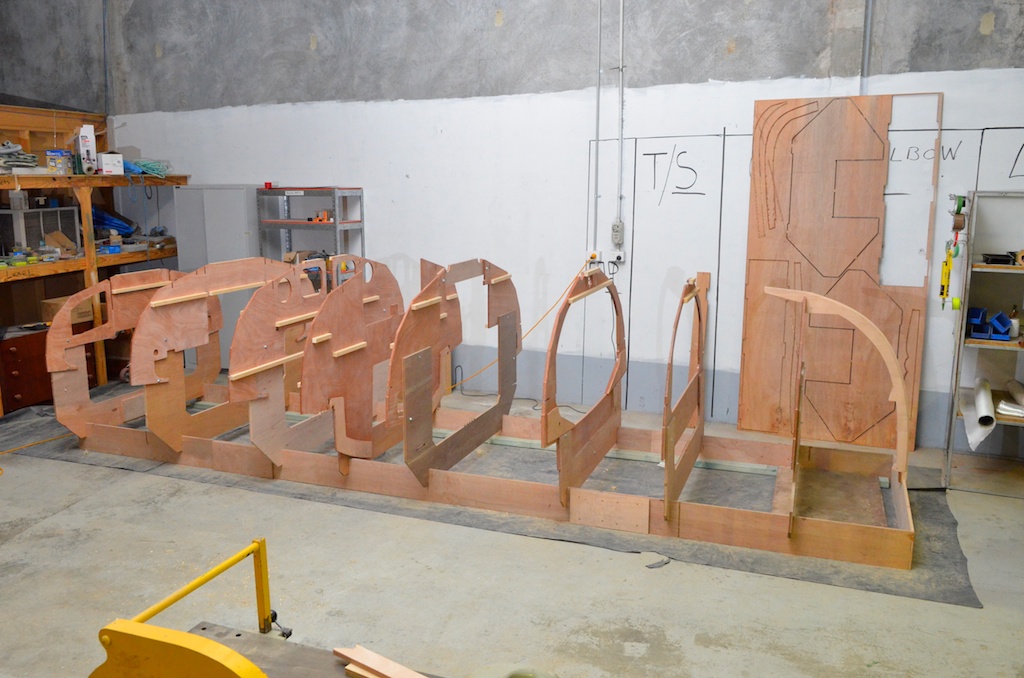
Glueing the keel in place with a small fillet on both sides, a larger fillet will be made later
After glue has set and clamps removed.
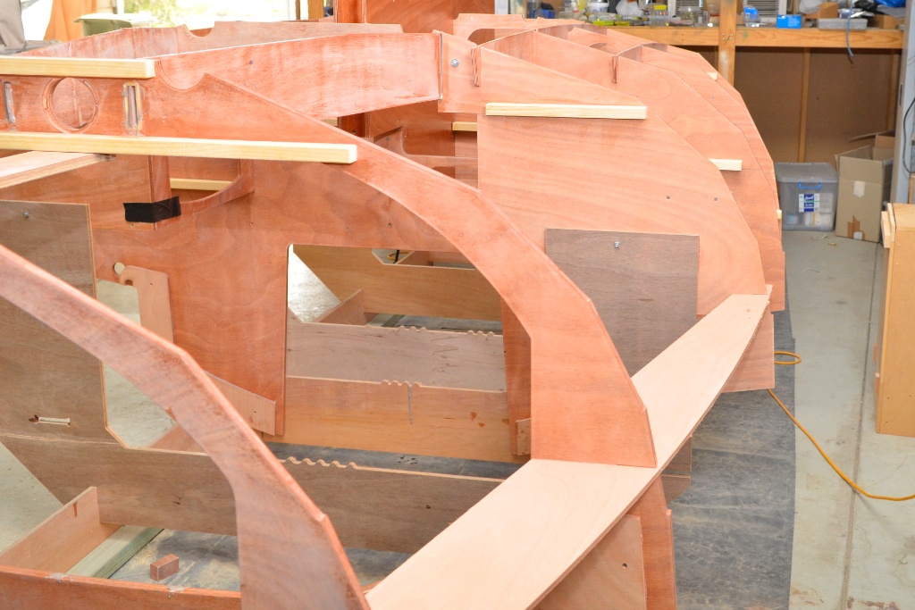
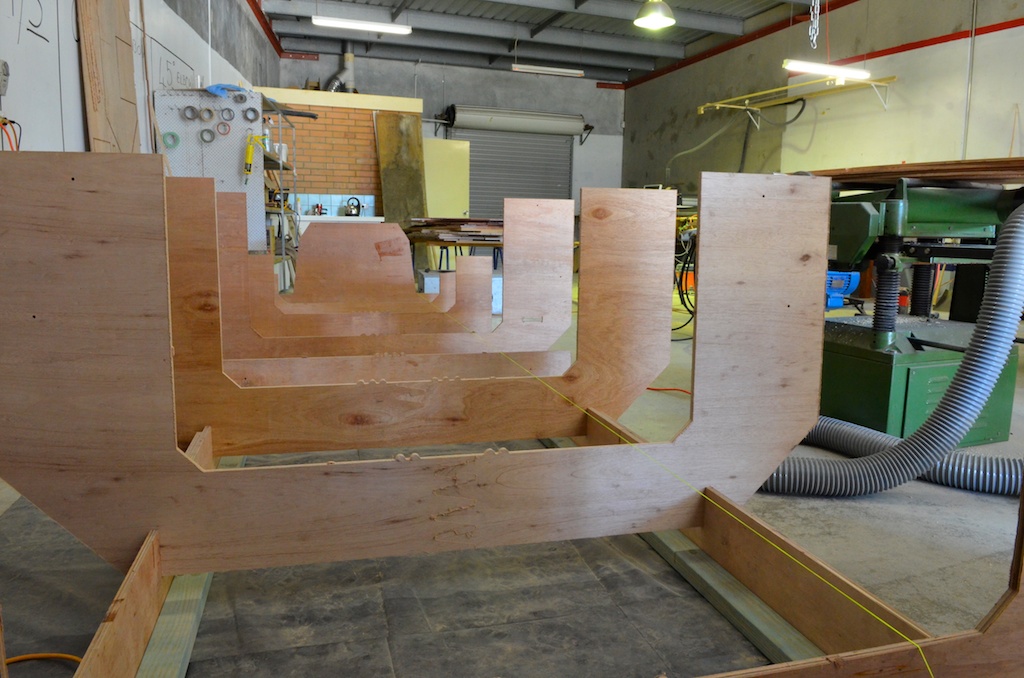
Side view.
View from aft and above showing hollow ends, the aft end is filled with high density foam the forward end with 120 kg of lead.
The keel base is solid timber, a pattern for which is in each kit, I haven't cut the sheets with the pattern in just yet so I just laid the wood in place and drew around it. The glue line in the picture is because I used some old Jarrah I had , If you are goung to use Jarrah on any boat then the keel is the place for it because it is very hard and heavy. I don't mind it being glued from two pieces as it will be well sheathed after.
Cutout around the centreboard case.
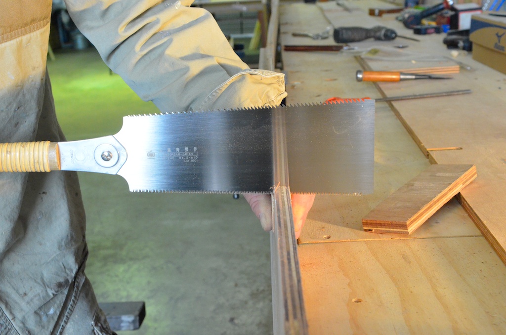
The outside also has "stems" whose dimensions are provided in the plans and which require hand shaping.
Marked and ready for bevelling.
Almost finished. Now the ends and base are removed to fit ballast and foam .
The plans call for 120 kg of lead to be inserted into the forward end of the keel, I have several bars of lead of different sizes which I cut and planed to size.
this piece for the front of the keel box
Fitted in position
I used a reciprocating saw to cut blocks, and also an electric planer for final shaping
Lead shavings from the plane, these are used to pack around the ballast later, and any leftovers are melted down into a new bar.
As more lead is fitted I use epoxy with glue powder mixed with lead shavings to fill the gaps
As the keel fills I used clamps to prevent the keel from splaying as I pack the shavings and epoxy in
I also need to finish the keel base.
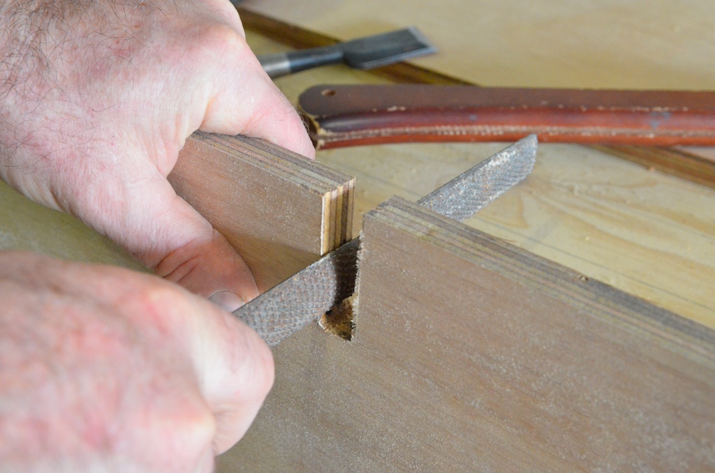
The cutout for the centreboard was finished with a flush cutter in the router, but this will mean that when I epoxy the base the insides will be a bit thinner than the case and will be prone to wear.Therefore I need to make the cutout a little bigger. First I use a radiusing bit in the router but one which rebates the radius a little,
Slot as it was after being routed flush with inside of centreboard case.
Next with recessed radius.
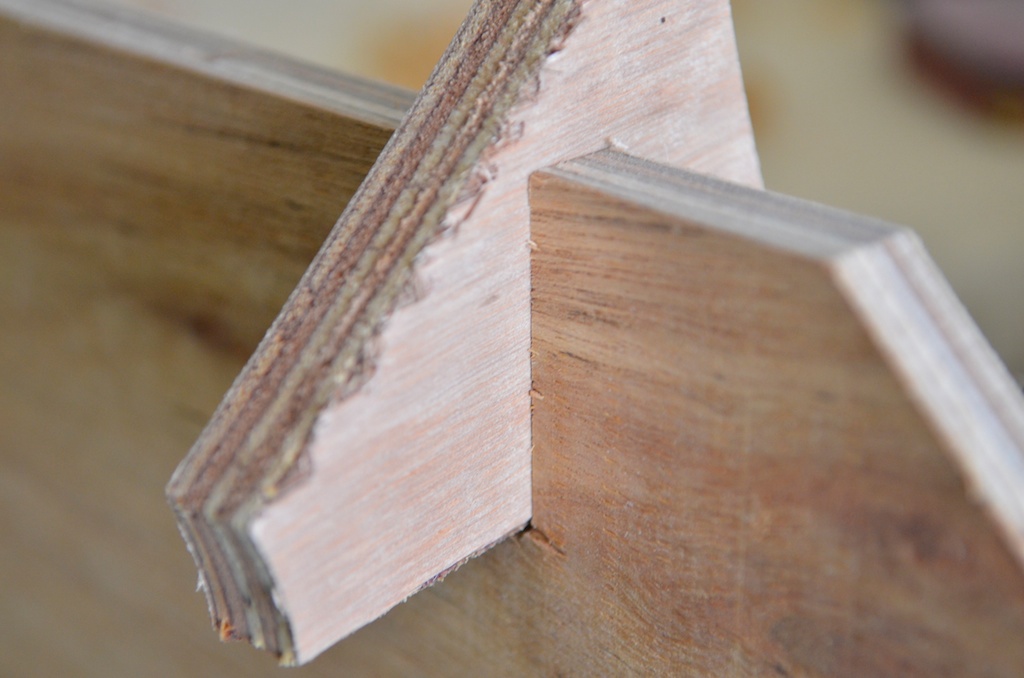
Then the plank is turned over and flush cut again with the bearing resting on the edge of the radius, leaving a slot approximately 1mm larger all round and a radius so I can lay sheathing cloth into the edge.